Several of the Gossen Metrawatt "Metrahit" multimeters from the Starline range (families METRAHIT E-series, S-series and the X-TRA) need an IrDA interface named USB X-TRA (or XTRA) to communicate with a PC.
Unfortunately this adapter costs like 300€ which is a bit out of range for a hobby user.
Then again, while things look different for older models like 18S, the newer Metrahit models like Metrahit X-Tra or Energy use a default IrDA interface.
There is a programmer's manual available for the Metrahit Energy, which names the protocol settings as 38400 Baud, 1 stop bit, no parity.
Now the problem is to get an IrDA adapter that uses 38400 baud on the IrDA side and that can be used as virtual COM port on the PC.
There are a few cheap Chinese RS232-IrDA adapters available, but they use 9600 baud on the IrDA side - even if they accept all typical baud rates on the PC side, this doesn't help here.
However there is a small IrDA board available called IrDA2 click which is essentially just a MCP2120 encoder/decoder, a TFDU4101 transceiver and a 7.3728MHz crystal.
When this board is configured to 38400 baud and connected to a PC with a serial to USB adapter (e.g. FTDI based), communication with a Metrahit multimeter is possible and even the MetraWin10 software works.
So while this worked, I wanted the whole thing on one small PCB which is the idea of this project.
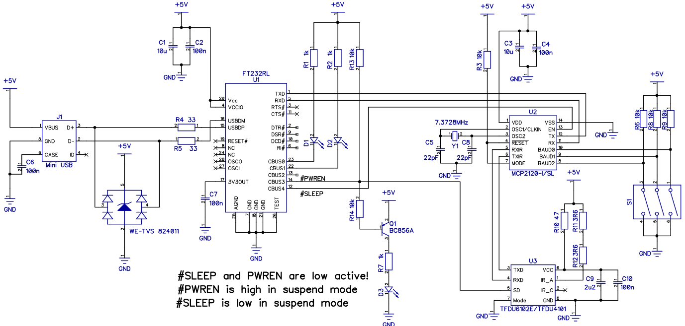
As in the IrDA2 click, the whole circuit is build around an MCP2120 IrDA encoder/decoder from Microchip. The mode pin is pulled up, so the baud rate can be only selected via the inputs BAUD0..2:
| BAUD2/1/0 |
IrDA Baudrate |
| 000 |
9600 |
| 001 |
19200 |
| 010 | 38400 |
| 011 |
57600 |
| 100 |
115200 |
| 111 | 9600 |
Note that for the PCB, the switch logic is somewhat inverted. The "on" position of each switch closes a connection to ground (0) while in the other positon, the pin is pulled up (1).
Additionally the switches are numbered 1 to 3 for Baud0 to Baud2. So to set "010" you actually have to set the switches to "3:ON 2:OFF 1:ON".
Since I had problems getting the TFDU4101 transmitter used in the IrDA2 click, I used a TFDU6102E instead. It has additional support for FIR with up to 4 Mbit/s, but this can be disabled by pulling the Mode pin to GND.
Note that this pin (7) is marked NC (not connected) for the TFDU4101, so the circuit should be compatible.
The resistor values are the recommended values from the TFDU6102 manual but should be ok for the TFDU4101 as well. R11 and R12 are used for controlling the current through the IR emitter.
To increase the output power of the emitter, the resistance has to be reduced and vice versa. For IrDA compliant operation, a current control resistor of 7.2Ohm (0.25W) is recommended at 5V.
Since 7.2Ohm is not a standard value from the EIA "E" series, the recommendation is to use two 3.6Ohm (0.125W) resistors in series.
The FT232 circuit is more or less the recommended default setting. There are two LEDs connected to CBUS0 and CBUS1 to show receive/transmit and another one to show the FT232 is enabled.
As the PWREN/CBUS3 output is low active (high in suspend mode), a PNP transistor is used to invert the signal and drive the LED.
The (low active) #PWREN line is also used to set the IrDA transmitter to standby mode to lower the powerdown current.
For the same reason the (likewise low active) #SLEEP line is connected to the enable input of the MCP2120.
For transient voltage protection, a TVS diode array was added to the in addition to the typical serial resistors.
Note that disabling the encoder/decoder MCP2120 and the transmitter/receiver TFDU6102 in suspend mode is important to reach less than 2.5mA in suspend mode.
I tested the current consumption when supplied with 5V (not connected to a PC) and measured 1mA with the ON/OFF/ON setting. With all three switches in ON position, it should be 2mA.
Schematic and Design were done with DipTrace.
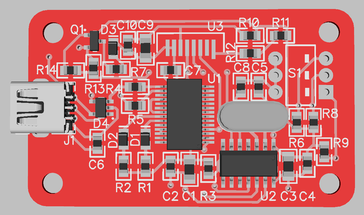
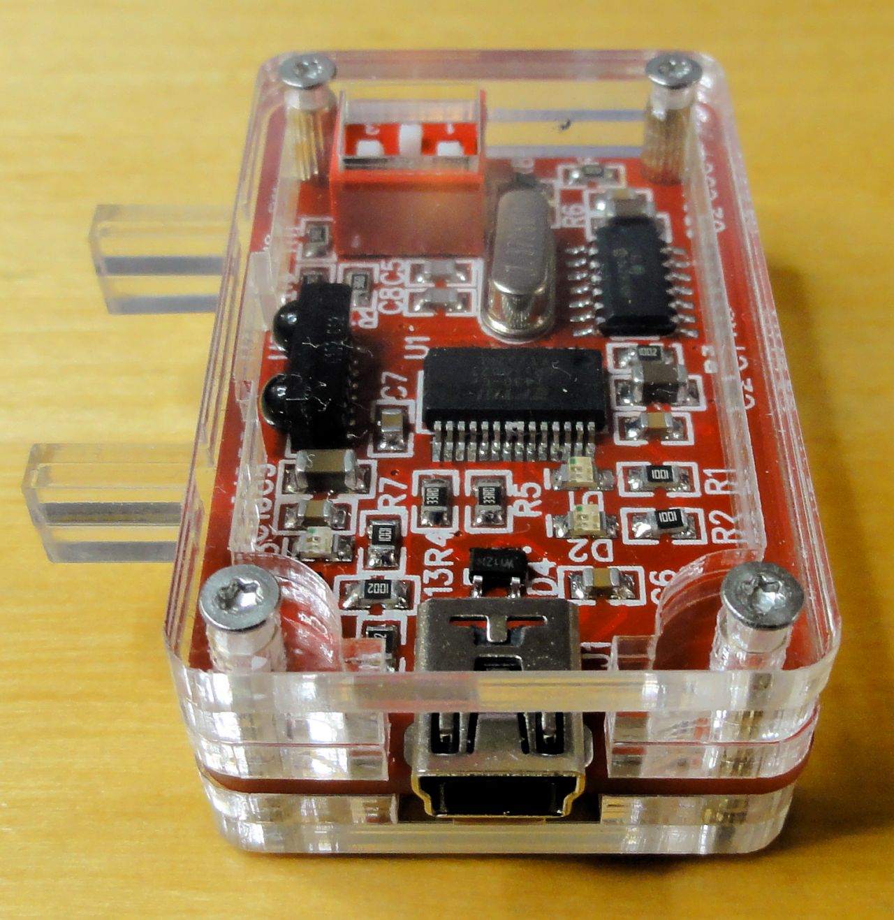
I tried to make it as compact as possible. The IrDA transmitter is on the top side. I decided to use mini USB instead of type B connector to save place (and micro USB is just too much of a hassle).
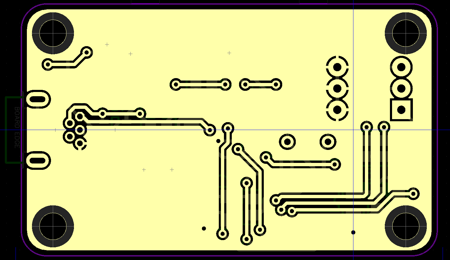
Just a preview of the final PCB.
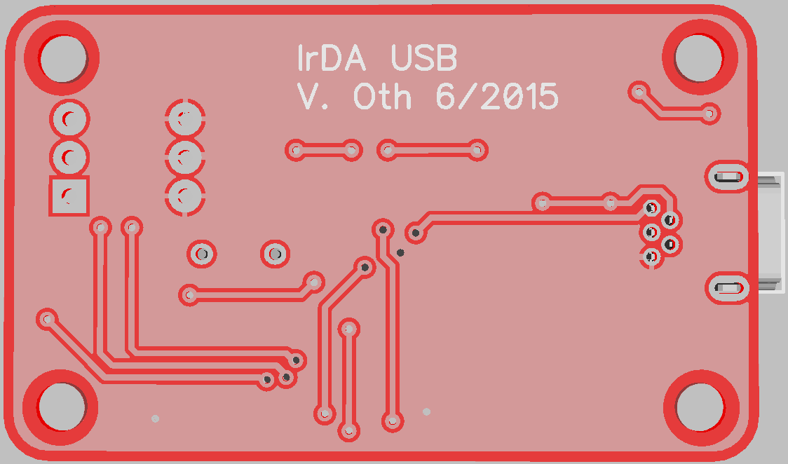
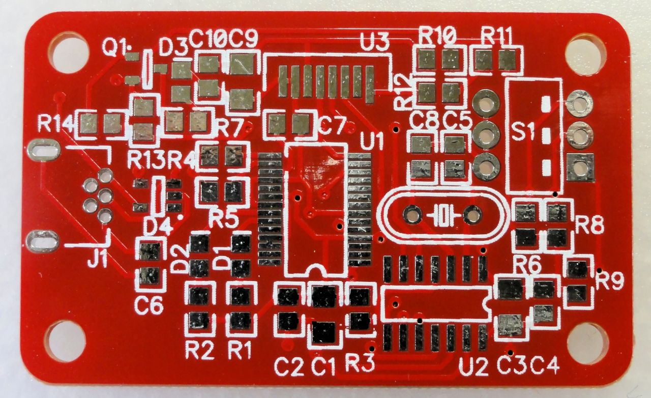
Ordered them at Elecrow, no problem as usual. Also the oval holes for the mini USB connector came out fine.
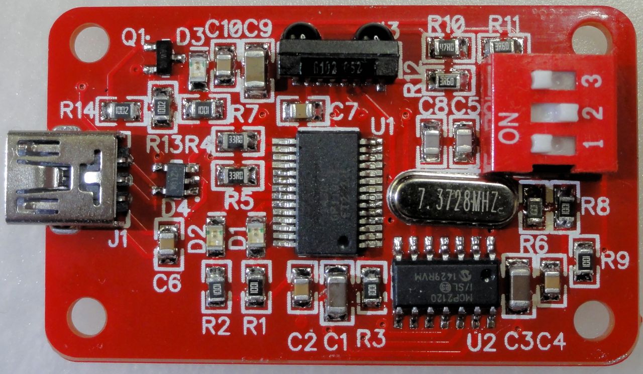
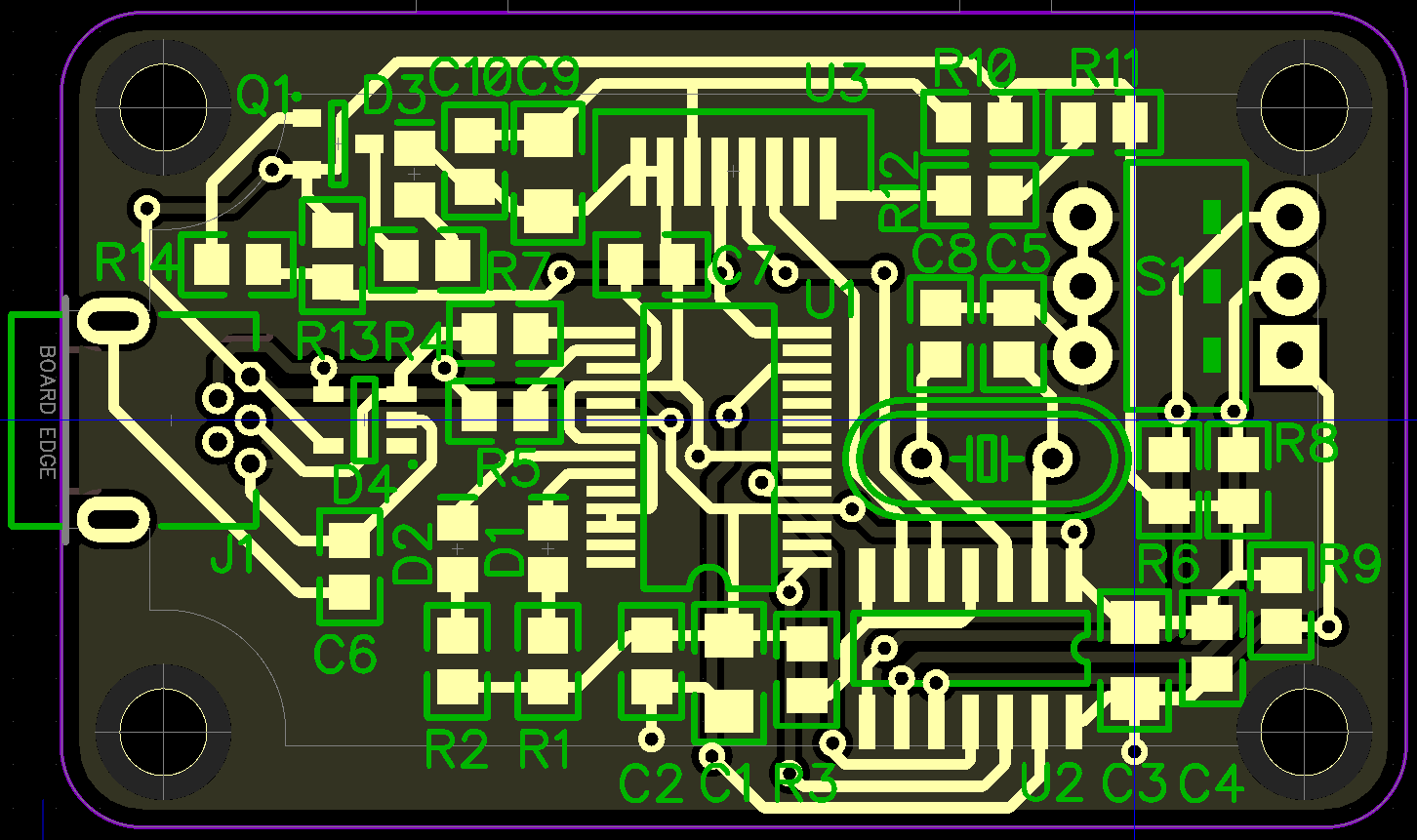
Admittedly, the DIP switch and the case of the Xtal touch, so the crystal is a little skewed, but yeah well.
For those with sharp eyes: don't be confused that some of the resistors in the picture are 1k instead of 10k. Actually I changed the schematic after I took the pictures.
The problem was that I noticed only a bit later that the 1k pullups would waste too much current to reach the USB suspend mode specification.
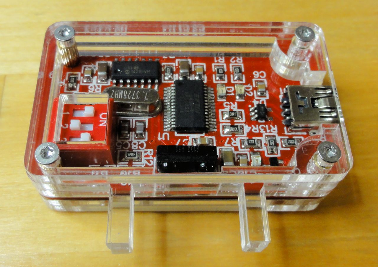
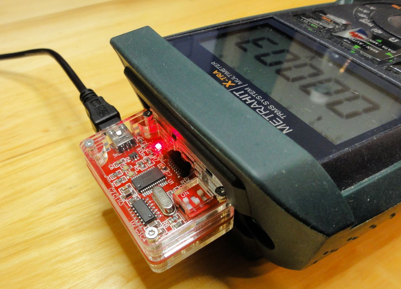
I designed an acrylic (cut) case that can be plugged directly into the meter. It consists of five 3mm layers plus the PCB and is held together by eight M2x6 T6 torx screws and four M2x10 brass spacers.
The CAD (DXF) files as well as some SVGs ready to order from Formulor can be found in the repository.
| Amount | Part | Type | Value | Source |
| 2 |
Ceramic capacitor |
SMD 1206 X7R |
10µF |
Voelkner |
| 5 |
Ceramic capacitor |
SMD 0805 X7R | 100nF | Voelkner |
| 2 |
Ceramic capacitor |
SMD 0805 NPO |
22pF |
Voelkner |
| 1 |
Ceramic capacitor |
SMD 1206 X7R |
2.2µF | Voelkner |
| 2 | LED | SMD 0805 | green | Voelkner |
| 1 | LED | SMD 0805 | red | Voelkner |
| 1 | TVS Diode |
WE-TVS 824011 |
5V | Voelkner |
| 1 |
Mini USB connector |
MUB1B5W |
socket, angled | Voelkner, Reichelt |
| 1 |
PNP transistor |
BC856A, SOT-23 |
Voelkner, Reichelt | |
| 3 | Thick film resistor | SMD 0805 | 1kOhm | Voelkner |
| 6 | Thick film resistor | SMD 0805 | 10kOhm | Voelkner |
| 2 | Thick film resistor | SMD 0805 | 33Ohm | Voelkner |
| 1 | Thick film resistor | SMD 0805 | 47Ohm | Voelkner |
| 2 | Thick film resistor | SMD 0805 | 3.6Ohm (or 3R3 & 3R9) | Voelkner 3R9 3R3 |
| 1 | DIP switch |
NT03 |
3x SPST |
Reichelt |
| 1 |
USB UART IC |
FT232RL, SSOP-28 |
Reichelt | |
| 1 | IrDA en-/decoder |
MCP2120-I/SL, SOIC-14 |
Voelkner | |
| 1 | IrDA transceiver |
TFDU6102E or TFDU4101 |
ELV | |
| 1 | Crystal | HC49 | 7.3728MHz | Voelkner, Reichelt |
Note: the linked sources are not necessarily the ones I used and most certainly not the cheapest ones.
They're mainly meant as reference. E.g. it should be clear that for a 1k or 10k pullup, you don't need 1% accuracy.
Make sure that the switches are set as shown in the pictures above (1: ON, 2: OFF, 3: ON) which sets the IrDA baudrate to 38400 baud.
When the circuit is connected to a PC through USB, the FTDI driver should be installed. Only when the FTDI is ready, the red LED turns on.
Start a terminal program, connect to the virtual COM port with 38400 baud (1 stop bit, no parity). Send commands like "IDN?", "TYPE?" and "POS?" followed by CR/LF and check that the meter answers.
You can also set the meter to send mode and check that values are received.
Now you can also try Metrawin10. Just connect to the COM port and search for a device. It should work without issues.
All files related to this project can be found in the BitBucket repository
https://bitbucket.org/fade0ff/irda-usb
This is a spare time project I did without any commercial interest.
Everything is released under the Creative
Commons CC-BY license.

In a nutshell this means that you can do share, modify and use everything
released under this license even for commercial projects.
You just need to give me appropriate credit, indicate what changes you
made and agree not to try to force a more restrictive license on my work.
See the CC BY license for details.