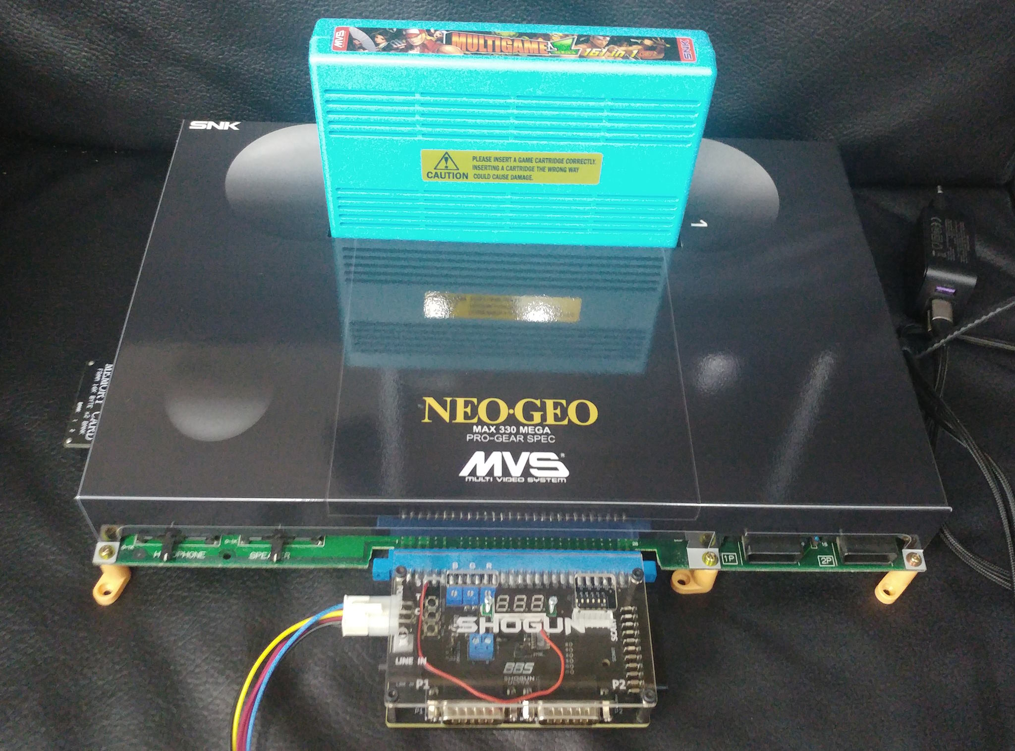
The Neo Geo was a very popular and powerful video game system in the 90s developed by SNK. It was sold as home console (also called AES nowadays) as well as used in arcade systems (also called MVS nowadays). The MVS arcade boards were supposed to be used in arcade cabinets but nowadays, many people want to use them at home and connect them to a TV or the like. To allow this, so called SuperGuns or MAKs (Mega Arcade Konsole) used.
A typical configuration looks like this:

While this works, there are some limitations that limit the usability:
The MV2F MiniMak tries to solve all of these issues by using a vertical design and splitting the functionality in a front and back PCB:
The front PCB is used for voltage/mode display, LED credits counters, two D-Sub connectors (note that the MV2F has joystick connectors but they are deeper than normal D-Sub connectors) and all the needed buttons.
It also can grab the two audio channels from the (MVS multislot specific) Jamma connector or use a headphone jack as supported by the multi-slot MVS boards.

The back PCB is used for voltage supply, creates 5V from a 12V supply by using a DC/DC module. It also performs the video (RBGS) level adjustment and features a SCART connector:

The multi-slot MVS boards are not fully Jamma compatible, specifically they feature two audio channels where the Jamma standard only supports one:
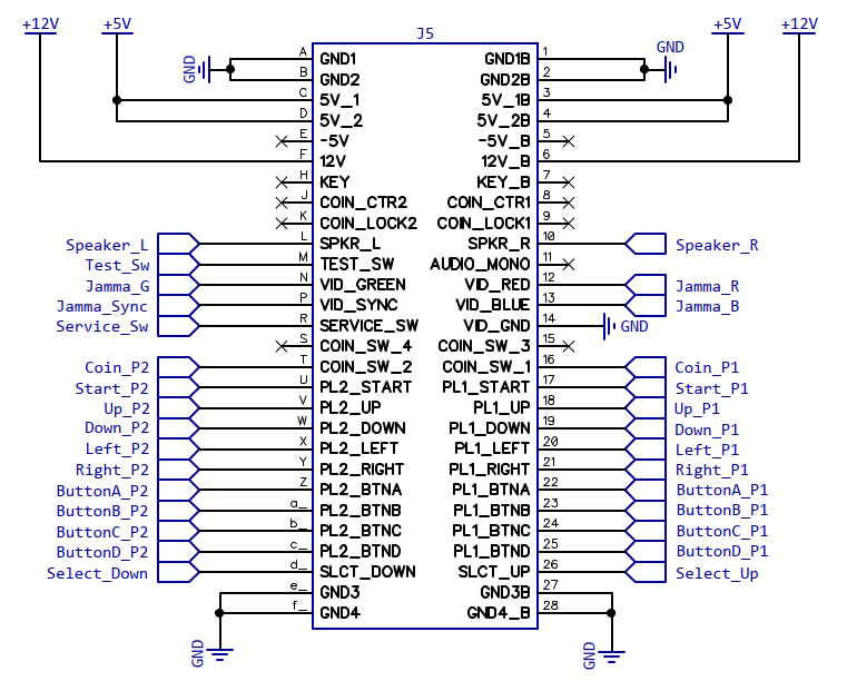
The front panel buttons are simply pulling the according Jamma connector pins to ground. No rocket science here:

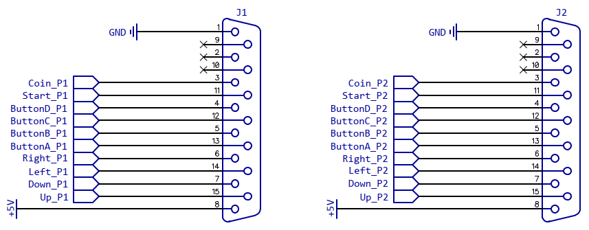
Likewise, the two D-Sub control ports are just connected to the according Jamma Pins:
The MiniMak allows to use the speaker left/right signals directly from the Jamma connector. A voltage divider and capacitor is used to convert the speaker driver outputs to a line level:
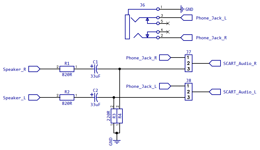
Using the jumpers J7 and J8, either the audio signals from the Jamma connector (jumper setting 2/3) or the signal from the audio jack input (jumper setting 1/2) can be used.
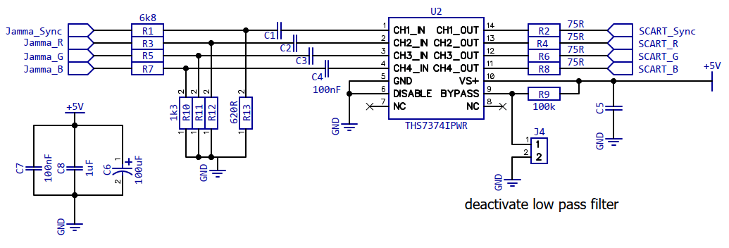
The MVS boards are meant to be connected to arcade CRT monitors where 5V levels were used for the RGB and Sync signals. However, the SCART standard defines much lower levels, e.g. 0.7Vss at 75Ohm for RBGS and 1Vss at 75Ohm for Sync.
To adapt the levels, a 4-Channel SDTV Video Amplifier THS7374 is used where voltage dividers at the input are configured to achieve the correct voltage levels.
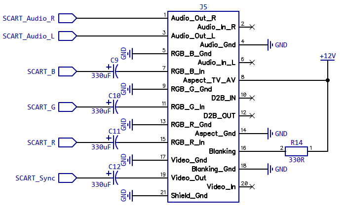
To force a correct 4:3 ratio, a level of 9-12V has to be applied to pin 8 (@>10kOhm load) and 1-3V (@75Ohm load) at pin 16 to force the use of RBG.
Therefore, the 12V supply is directly connected to pin 8 and through a 330Ohm resistor to pin 16. The 330Ohm resistor and 75Ohm load form a voltage divider and the resulting voltage is ~2.22V (12V*75Ohm/(330Ohm+75Ohm)).
Also, for full SCART compatibility, 330µF capacitors are used for AC coupling the RBGS signals.
This is actually a bit of a gimmick as it doesn't really show the current credits output by the MVS board but checks button presses on the coin and start switches and counts up when coin is pressed and down when start is pressed.
Also note that only the US BIOS (or region setting) supports separate coin slots for the two players. The Japanese and European BIOS (or region settings) only support one common coin slot. This is accounted ffor with a mode setting, which is discussed later.
To control the four 7 segment LEDs, a cheap Chinese LED driver called TM1637 is used. It is quite wide spread and used on a lot of 7 segment LED displays sold on AliExpress and the like:
 OLELED
I first thought about using one of these small LED voltage displays sold on AliExpress but then decided that an OLED display would be more versatile and easy to use since I need a microcontroller for the LED display and button processing anyway.
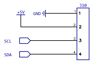
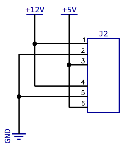
Not much to see here apart from a four pin connector that supplies the OLED module with 5V and connects the I2C bus (SCL/SDA):
The OLED display used is a monochrome 128x64 pixel display with an SSD1306 display controller.
I used the NXP LPC824 which is a 32bit Cortex M0+ controller that doesn't need any external components, features an ADC converted and I2C peripheral amonst many other things. It's a bit "over the top" for this purpose, but it was the easiest choice for me.
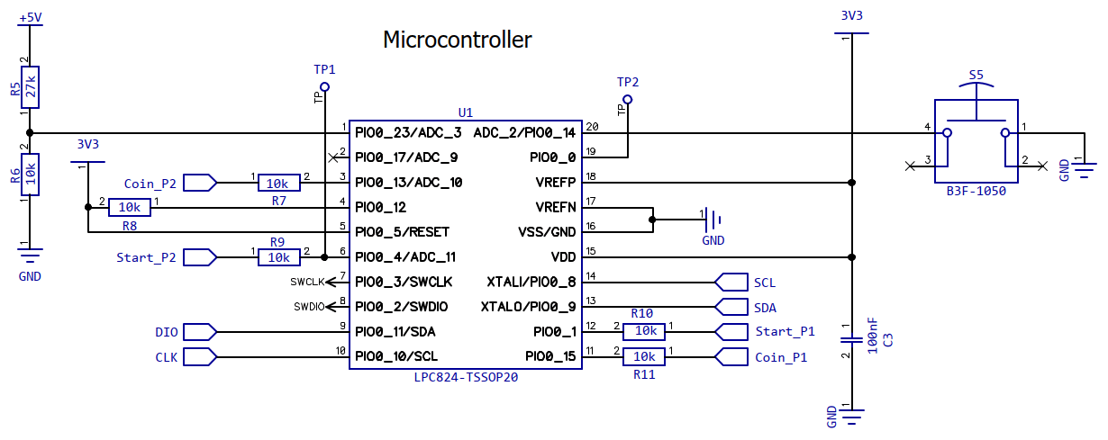
The coin and start switches and an internal mode switch are connected as inputs. SCL and SDA are used to communicate with the (I2C) OLED display and DIO/CLK are used to communicate with the LED controller (proprietary SPI-like protocol).
The voltage divider connected to P0_23/ADC_3 is used to convert voltages up to 12V to the 3.3V ADC reference voltage of the LPC824 ((27k+10k)/10k = 3.7 = 37/10).
The original idea was to use a cheap >=12V to 5V DC/DC module and screw/solder it to the back pcb.
This one was the first one I tried, but it was a dud.
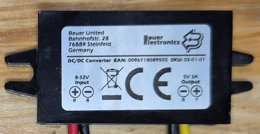
It didn't meet the specs from its datasheet - without load, the voltage was 5.1V which would have been quite ideal, but between 1.2A and 2.1A, the voltage jumped up to 5.36V which is too high for an MVS board.
Don't use this one since it has a fault voltage/load regulation!
This one seem to work better and has the same form factor, but note that the outputs are inverted:
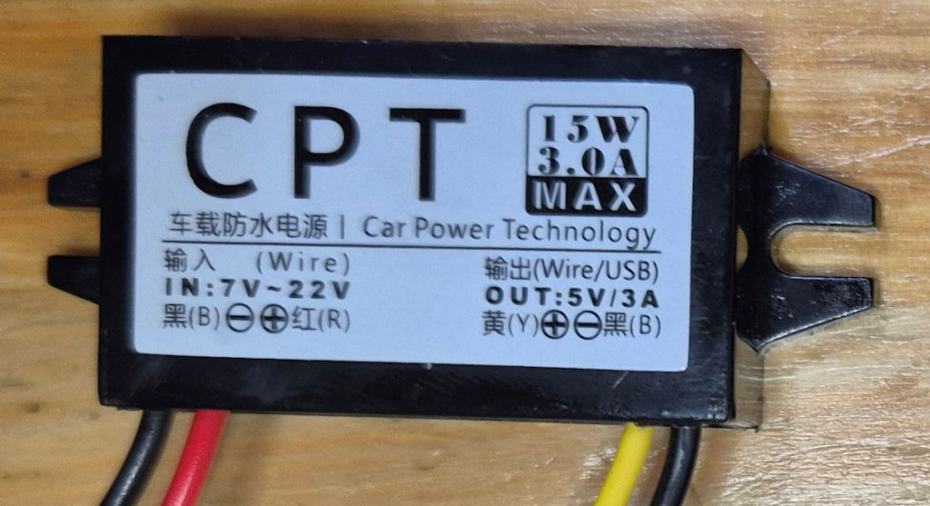
For my initial prototype, I decided to use a different type though:
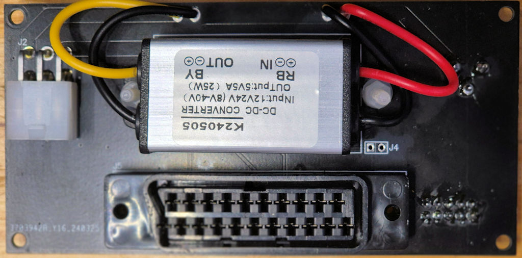
Mechanically, it's not ideally fitting, but it delivers up to 5A and has a proper load regulation. But it's very close to 5V without load and due to the unavoidable voltage drop over the wiring, the voltage at the Jamma connector was always quite a bit under 5V,
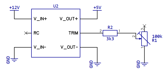
Therefore I decided to design a small DC/DC daughter board using the Mean Well SKMW20F-05 converter. It's an isolated converter, which is totally pointless in this usecase and it's quite expensive, but at this point I was not willing to mess around with cheap converters anymore and wanted to have a trimmable one with good specs from a reliable company:
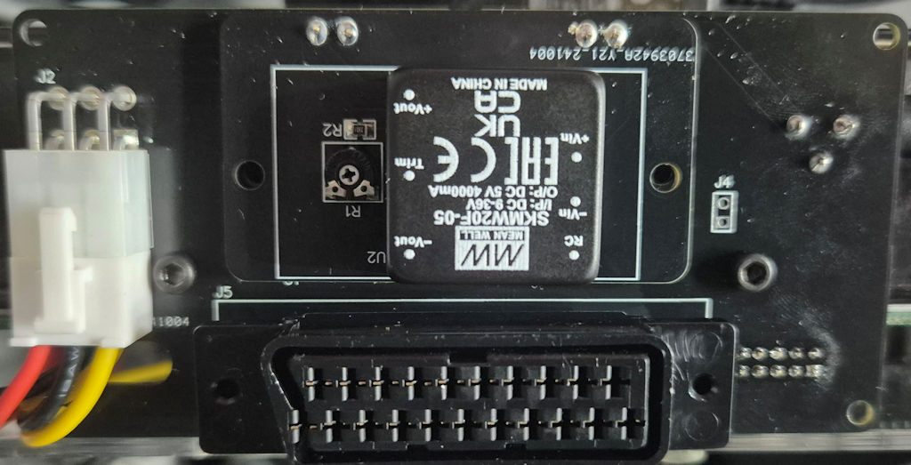
R2 is there to lmit the maximum voltage to around 5.5V, so using the 100k trimmer, it can trimmerd betweeb ~5.05V and ~5.5V.
I trimmed it to ~5.1V without load, so the voltage stays slightly above 5V in a full load condition (~1.5A).
For the front panel, I decided to try the JLCPCB multi-color silk screen. The only software that supports this format at the moment is EasyEDA Pro, so I designed the front panel with this.
I came up with this design for the front panel (but you can easily change this with EasyEDA Pro):

Note that when ordering, you need to select ENIG and white (!) PCB color, then under "Advanced Options" you need to select "EasyEDA multi-color silkscreen".
To mount the back PCB to the case of the MVS2F, I designed a mounting bracket that can be 3D printed:
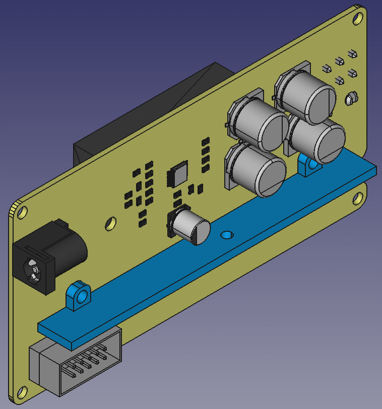
The FreeCAD design file and STL file can be found in the repository.
To connect the video and audio signals from the front to the back panel a 10 pin flat ribbon cable is used.
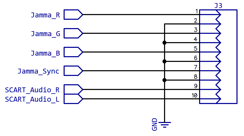
Make sure to connect pin 1 on both connectors with the same wire.
For the power supply (5V, 12V and ground), 6 pin Molex "Mini-Fit Jr" connectors are used. I first tried to use a ready-made cable, but had to reconfigure it and was disappointed by its resistance despite its "18AWG" rating. Therefore, I crimped my own cables with actual 18AWG wires:
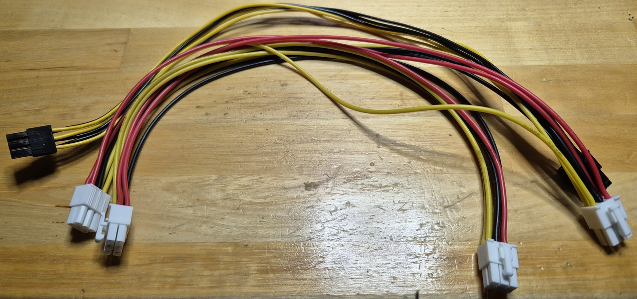
Again, be sure to connect pin 1 with pin 1 etc on both sides, else you will fry the front pcb:
The voltage is sampled every 1ms but the OLED is updated only every 500ms with a slightly filtered value in normal mode. The 1ms sample rate is used to calculate a minimum, maximum and moving average value over 1s (i.e. 1000 values).
Also the coin and start buttons as well as the internal mode buttons are captured every 1ms with a bit of debouncing.
Configure J7/J8 to use the audio signals from the Jamma connector (jumper setting 2/3) or the signal from the audio jack input (jumper setting 1/2)..
Connect as 12V power supply to the DC jack on the back pcb. I'm using a Mean Well SGA60E12-P1J.
Press the mode button for <1s to switch the voltage display mode (large display of a slightly filtered voltage or the min/max/average mode).
Press the mode button for >1s to switch between US mode (two credit slots) or JP mode (1 common credit slot).
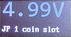
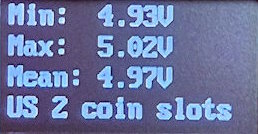
In US mode, each player has separate coin/start buttons affecting the player specific credit counter, in JP (Japanese/European) mode, both credit counters will display the same value and both player's coin/start button will affect the common credit counter.
Each activation of a coin button increases the according coin counter, each press of a start button decreases the coin counter.
Press player one start for >1s to reset the credit counters.
Before attaching the front PCB to the MVS connector, be sure to connect the flat ribbon cable and molex connector. It will be very difficult or even impossible to do this with the front pcb already attached.
Also don't attach the front PCB to the MVS board while the front panel is mounted. Apply pressure only to the backside ot the Jamma connector, not on the sides of the PCB to avoid flexing of the PCB.
When removing the front panel use a screwdriver or similar tool to provide leverage at the edges of the Jamma connector to carefully remove the front PCB.
There is an SWD debug connector under the OLED display. it can be used to reprogram the microcontroller with any appropriate flash/debug tool, e.g. LPC-Link or Segger J-Link.
The schematics and PCBs (apart from the Front Panel) were designed with DipTrace. There is a free version available with up to 300 pins or even 500 pins if you register (this design uses way less than that).
All files related to this project can be found in the BitBucket
repository
https://bitbucket.org/fade0ff/minimak
This is a spare time project I did without any commercial interest.
Everything is released under the Creative
Commons CC-BY license.

In a nutshell this means that you can do share, modify and use
everything released under this license even for commercial projects.
You just need to give me appropriate credit, indicate what changes you
made and agree not to try to force a more restrictive license on my
work.
See the CC BY license for details.