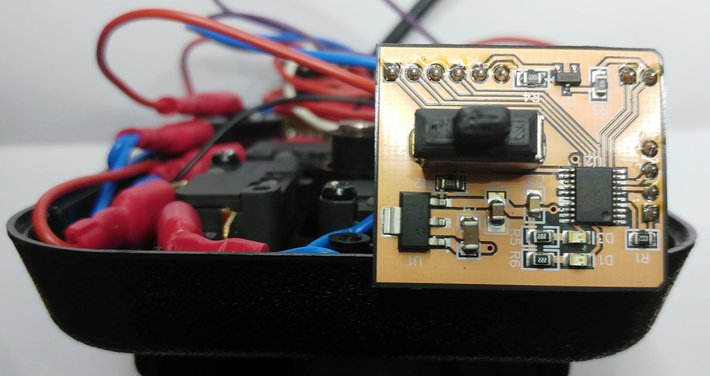
While there was a classic version of the Speedlink Competition Pro sold for a while, the only version available right now is the now is the USB version which works fine on a PC but not on a classical computer like C64 or Amiga. While it can be quite easily reworked to classic mode by connecting the switches directly to a DB9 cable (still sold as Sega MegaDrive extension cable), the rapid fire functionality is removed since it's on the same circuit board as the USB interface. So I designed this little PCB to replace the circuit board.
Instead of messing around with some RC oscillator or 555 timer, a small microcontroller, namely the LPC824 is used. This also opens the possibility to implement an additional feature, namely to support the 2nd fire button for C64 and Amiga. While all directions and the first fire button are always switched to ground and pulled up internally in the computer, the 2nd fire button of the C64 is an exception. Since it's internally connected to the SID input PotX which was originally designed to read an analog value from a paddle, it's actually switching to 5V. Actually, the details of this are a bit more complicated. The SID's POTX/Y inputs are not conventional AD converters but are actually digital input/output pins with an internal comparator and a capacitor. The paddles originally connected there used potentiometers connected to 5V. The pins are frequently switched to ground to discharge the capacitor and when switched back to high impedance mode, the time is measured until a voltage threshold is reached. The external resistance of the potentiometer determines the time to reach the threshold which results in the X/Y position measured.
When connecting a button to POTX, the high resistance against 5V can be simulated by leaving the pin floating. The low resistance to 5V should not be lower than 300Ohm since the SID periodically pulls the POTX line to ground and if the button would connect to 5V directly, this would cause a short circuit current into the SID which could damage it. Therefore the following switchable pullup is used for the 2nd Button:
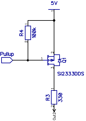
So in C64 mode, this pullup is switched on and off to create the low
resistor value by creating a 330Ohm path to 5V or leave the pin floating.
In Amiga mode, the pullup is deactivated and button 2 switches to ground
(open drain) just as button 1. Note that the two outputs OUT1 and OUT2 for
the buttons 1 and 2 are true open drain outputs which are fully 5V
tolerant.
Since the Competition Pro has four buttons but the C64 only supports one or two (mainly for the C64 game system or new releases), it's suggested to connect the two large buttons to IN1A and IN1B and the two small buttons to IN2A and IN2B. Of course you can choose to wire them differently. Just note that the A and B buttons are ORed internally. So if you press either IN1A or IN1B, this will cause cause a button press signal on OUT1 and the same for IN2A, IN2B and OUT2.
To switch between C64 and Amiga mode, press the button (switch to ground) connected to input pin IN2A when the joystick is powered on. Then the button connected to IN1B selects the mode: button pressed (low) selects C64 mode, button unpressed (high) selects Amiga mode. Using the Amiga mode with a C64 doesn't damage the SID, but the button simply won't work. Using C64 mode with an Amiga should cause the button to behave inverted but I didn't really test that.
Whatever you selected last in stored in NVRAM and used until the mode is switched again. Actually there is an LED to display the mode (C64 mode: LED on) and one for the rapidfire switch as well. Unfortunately, unless you have a transparent case, these are not really visible.
There is a little quirk regarding IN2B. I noticed too late that pressing N2B/PIO0_4 during power up seems to block the program execution. This behavior is not really documented anywhere and therefore I'm still unsure if this is due to the TRST (JTAG Reset) or WAKEUP functionality. I suspect the device somehow assumes it's in boundary scan when this pin is low during startup, so I couldn't use it for mode selection.
The main functionality is the switchable rapid fire for button 1. It only
works for the first button as this is the only thing that makes sense.
AFAIK the 2nd buttons is never used in a way that rapid fire would be
helpful. Note that the frequency is set to 25Hz which is supposed to be
the "ideal" frequency. There currently is no way to change that other than
to change the software.
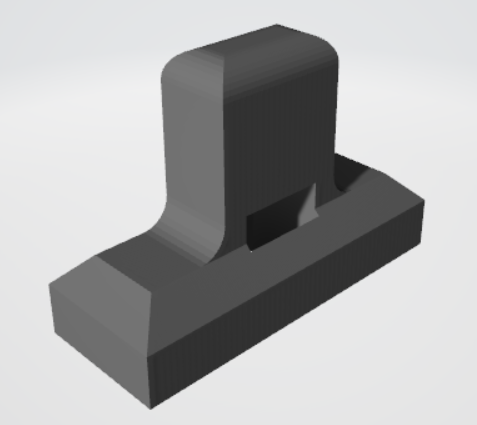
Since I couldn't find any switch with an actuator that would be reachable
from the outside, I decided to go for a Tru Components CSS-1202 switch
with a 4mm actuator and 3D print and extension that can be reached from
outside the joystick case.
All files related to this project can be found in the BitBucket
repository
https://bitbucket.org/fade0ff/rapidfire
This is a spare time project I did without any commercial interest.
Everything is released under the Creative
Commons CC-BY license.

In a nutshell this means that you can do share, modify and use
everything released under this license even for commercial projects.
You just need to give me appropriate credit, indicate what changes you
made and agree not to try to force a more restrictive license on my
work.
See the CC BY license for details.