The Neo Geo was a very popular and powerful video game system in the 90s developed by SNK. It was sold as home console (also called AES nowadays) as well as used in arcade systems (also called MVS nowadays). Both, the home console and all the arcade boards which actually had game ports (the later one slot board didn't), used a 15 pin D-Sub connector as joystick connector. The according joysticks (also called joyboards) were only sold for the home consoles are now rare and usually also not in best shape. Still, it's not uncommon to pay 100€ for an original joystick in so-so condition. While it's relatively easy to create your own DB15 arcade stick, there is quite a bit of mechanical work involved, they are usually somewhat clunky and with a proper joystick and switches, also not very cheap.
This adapter is supposed to solve this issue by allowing to use more or less any HID USB joystick or gamepad with your Neo Geo hardware.
It should work with every joystick and joypad that reports as HID desktop joystick or gamepad. It actually also support keyboards to some degree.
There is built in support for several common USB Neo Geo joysticks and gamepads, but you can define your own button/direction setup and store up to 8 setups in NVRAM.
I used Arm Cortex-M controllers from NXP (e.g. LPC824, LPC1549 etc.) in the past, but couldn't find an affordable, smallish controller with USB Host suppport and 5V tolerant pins in their portfolio.
Therefore I looked into the STM32 family from ST and first found the STM32G0B0CET6 (Cortex-M0+, LQFP48). I quickly found USB Host examples for this controller and actually started (nearly finished) a PCB design for it.
However, when looking up prices at Mouser, I was surprised to see that the "high performance" STM32H503CBT6 (Cortex-M33, LQFP48) was quite a bit cheaper. When comparing the data sheets, I also noticed that I overlooked that the STM32G0B0 would need an external crystal for USB operation and its datasheet stated only 1k flash cycles - which sounded problematic since I was aware that I would need to implement a NVRAM/EEPROM simulation in normal flash due to the absence for internal EEPROM.
Now, the STM32H503 features a specific internal 48MHz oscillator for USB without external crystal and its flash is specified for 10k flash cycles. It also has more 5V tolerant pins. So, even if using a "high performance" Cortex-M33 seemed a bit weird for such a small project, it was easy to choose the STM32H503CBT6 as it has 10 times the flash cycles, can run completely without external oscillators, has the better core and is even cheaper.
Apart from the microcontroller, there are only a few other active components used:
As a real Neo Geo joystick switches the according pins for the directions and buttons to ground and they are pulled up to 5V by 1k resistor networks on the Nep GHeo PCB (actually CRE401 R/C arrays are used), the STUSB2DB15 mimics this by configuring all output pins (connected to the DB15 connector) as open drain outputs without pull device.
An original Neo Geo joystick or gamepad supports four directions, four buttons (A,B,C,D) plus the select/coin and start buttons.
To also allow using the gamepad on MAKs/Superguns (hardware to make Jamma based arcade boards usable without a full arcade setup), I added two more buttons E and F.
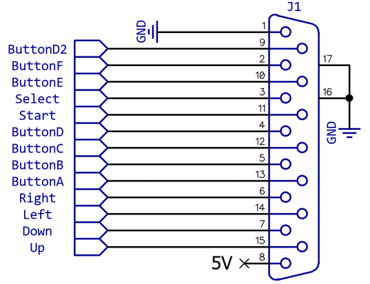
The two additional buttons E and F are located on pins 10 and 2, which are actually outputs on the home console. Also pin 9 is an output on home console.
Apparently, these pins are also used on the home console to detect specific controllers, e.g. a Mahjong Controller and also to switch e.g. the input matrix on these controllers.
Obviously, the original Joyboards switch down Button D (Pin 4) when the output on Pin 9 is switched to ground. To mimic this behavior in the simplest possible way, there is a jumper J2 to shorten these pins. It's probably not needed, because a normal joystick is supposed to be the default if the detection fails.
Note that even though the three output pins 2, 9 and 10 on the home console are open collector outputs (without pull devices) and switching them to ground should do no harm, I added the three 330Ohm resistors R2, R3 and R5 for these outputs to add a little bit of additional protection. If you still don't like the idea of buttons pulling these three lines low, just don't place the resistors.
My initial idea was to quickly throw together a setup with STM32CubeMX, including USB middleware, the I2C driver for the display and an EEPROM simulation. This was somewhat optimistic to say the least and in the end it took me around two weeks to get the software running.
My first shock was that the driver "USB_HOST" available for the STM32G0B0 and many other controller was not available for the STM32H503. Instead, CubeMX offered only the middleware "USBX" but didn't let me select it unless I also selected "Azure RTOS ThreadX". I wasn't too happy with this but had to accept it at this point. However, the code that CubeMX created was not running. Actually it was designed in a way that it could never work. E.g. the ThreadX initialisation called USBX functions which got stuck in an error handler because they expected the ThreadX initialisation to be already finished. When I worked around this, it got even worse: the USB interrupt handler called functions to allocate memory which got stuck at a Mutex function that explicitly checked that it must not be called from an Interrupthandler. After more than 8 hours all I had was a steaming pile of Yak excrements that somewhat reacted when I plugged in or removed a mouse. Side note: the ST USBX host middleware supports only HID mice and keyboards. No joysticks or things like that.
At that point, I was somewhat desperate and began again to search for any kind of working USB host example for USBX. Fortunately, I was finally able to find exactly one example called "Ux_Host_HID_Standalone" for an evaluation board called "STM32H573I-DK" which used USBX without ThreadX or Azure RTOS. So I merged the USB code from this example into my project, removed all stuff related to ThreadX and Azure RTOS and finally at least I could read data from a mouse. Then of course, I had to implement the whole joystick class functionality based on the mouse implementation, but that was actually not so bad compared to the effort to get a running USB Host driver.
Because I wanted to store joysticks setups persistently and the cheaper STM32 controllers all don't seem to have an integrated EEPROM, I tried to integrate an EEPROM simulation called "X-CUBE-EEPROM" provided by ST. However, when using the driver for the STM32H53xx family (which was the closest I could find for the STM32H503), it was not compilable. Long story short: at this point I noticed that the STM32H503 doesn't have a specific 16bit writable "high cycle flash" that is mentioned as feature for the STM32H5 family (and therefore expected by the EEPROM simulation for the STM32H53xx driver). While its normal flash is banked and supports 10k cycles, it can be only written 128bit wise. So I configured/patched the driver accordingly, and it worked to some degree, but I was not really happy with it for several reasons. One of the reasons was that I noticed that after each reset it would write at least one 128bit (quad)word to flash. And the only condition that could have avoided this was only stored inside an automatic local variable (i.e. not at all). This is when I lost my confidence in this approach and decided to port my own quick'n'dirty NVRAM-Emulation from an LPC824 project. It was a bit of a hassle as the STM32H5 family doesn't support blank checks and I needed to change quite a few things because of the 128bit flash access, but finally I got it to work.
In a nutshell it uses the last two 8K sectors in flash to write a configuration structure (containing the 8 setups) plus a magic word ("0xdeadbeef) and a 16bit CRC rounded up to the next 128bit address. So one entry is e.g. 144 bytes which means that 56 entries can be written one after the other to one 8K sector. If the sector is full, the other (erased) sector is used to continue writing and the previously used sector is erased. With 2 sectors, 56 entries per sector and 10k flash cycles, this should be good enough for more than 1 Million NVRAM writes, which seems more than sufficient.
After all the other issues, I was surprised to see that the I2C driver was working and pretty much OK. I ported over my minimum SSD1306 driver for the OLED from my LPC projects where I used my own optimized I2C driver, but I found a solution with the ST driver that is at least close to what I had, so that was relatively straight forward. I also ported over a minimum "time task" implementation from my LPC projects which I needed to implement the state machine for connect, disconnect, configuration mode etc.
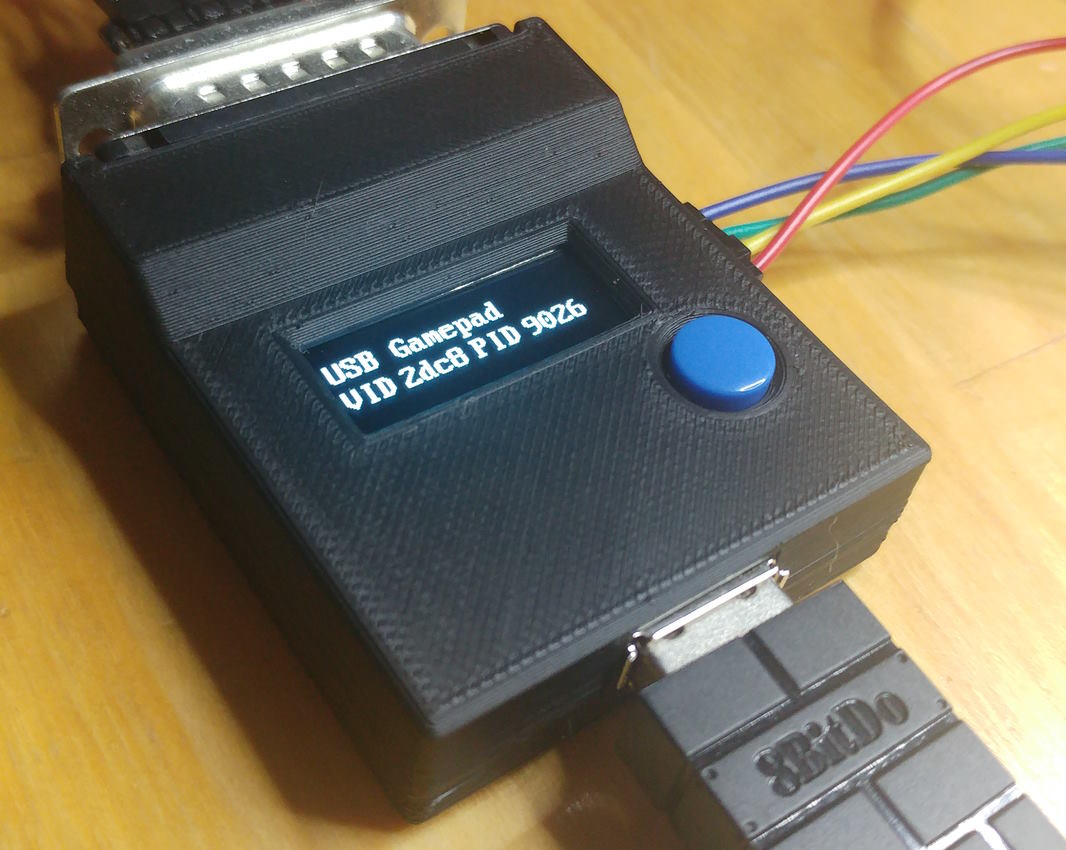
I also designed a case which can be 3D printed.
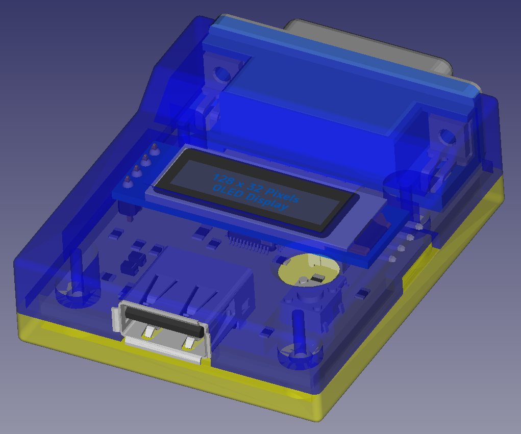
The FreeCAD design files and STL files can be found in the repository.
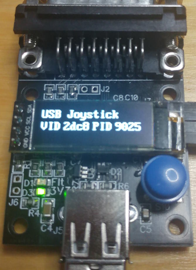
Connect the STUSB2DB15 to a DB15 input of your Neo Geo hardware or MAK/Supergun using an appropriate extension cable. The display shows a startup message and the green power LED is lit.
Now insert any HID USB joystick or gamepad with at least six buttons or an USB keyboard if you don't have a joystick/gamepad at hand. The display should change to either "USB Gamepad", "USB Joystick" or "USB Keyboard" and the USB VID/PID should be displayed in the next line.
If this is not the case, then the device you plugged in doesn't report itself as HID desktop joystick, gamepad or keyboard. if the device is supported "out of the box", there was a setup stored before for this device or if the default setup works for you, you are read to go.
The following devices are supported "out of the box":
If there is no default or previously stored setup found for this device, the following default setups are used:
For joysticks and gamepads, the axes X/Y/Z, RX/RY/RZ, Simulation Control X/Y/Z, a hatswitch and up to 32 buttons are supported.
Each axis can create two direction events: "high" (is the value was > 192) and "low" (if the value was < 64). Other values mean "no direction" (neutral position). This seems to work well for all the joysticks I tried which deliver either 127 or 128 in neutral position.
The hatswitch is supposed to deliver values from 0..7 for the 8 directions, starting with Up (0), continuing clockwise until "Left/Up" (7). Any other values means "no direction" (neutral position).
The keyboard support is a bit of a gimmick and last resort if you don't have any fitting USB controller at hand. It might also come in handy for people using (mechanical) keys to create fight sticks and the like.
Right now only "normal" keys are supported for several reasons, but this includes the cursor keys, function keys, Space and the like. However, modifier keys like Shift, Alt and Ctrl are not supported at this point.
Every scan code between 0 and 127 is supported which should be sufficient for all normal keyboards.
If a device is plugged in and recognized, pressing down the menu switch on the STUSB2DB15 for 1s enters the configuration/learning mode. In this mode, you are requested to press up, down, left, right etc. where you are expected to press the according directions or buttons on your HID device. As soon as exactly only one direction or button is pressed, "OK" is displayed and if you release the direction/button, this continues with the next direction/button. You can skip to the next step at any point by pressing the menu button shortly (i.e. for less than 1s). Finally, you're asked to press the menu button for 1s to store the setup in NVRAM. This only takes an instant, but it would be wise to not remove power as this could cause corruption of NVRAM. As with all the other steps, you can also skip storing in NVRAM if you press the menu button shortly (<1s).
Up to 8 setups can be stored in NVRAM where five are already pre-configured and 3 are empty. If one of these 8 setups uses the same USB VID/PID, this setup is overwritten without touching the other ones. Otherwise, an unused setup is overwritten. If all 8 setups are already used, then the one is overwritten which was stored as first of the 8 setups.
If you press the menu button for at least 5s (whether a device is connected or not), the message "Init NVRAM? is displayed. As with the storing in NVRAM, you can either skip this by pressing the menu button shortly or erase the whole NVRAM by pressing the menu button for >=1s. This will erase all stored setups and reset the STUSB2DB15 to its initial state (i.e. with the default setups). This should usually not be necessary but might be helpful if the NVRAM got corrupted at some point.
The schematic and PCB were designed with DipTrace. There is a free version available with up to 300 pins or even 500 pins if you register (this design uses way less than that).
In the schematic, I used a B3F-1055 (6x6mm) tactile switch with a yellow plunger but of course a B3F-1050 with an ivory plunger would be OK as well. Or more or less any other 6mm tactile switch with protruded plunger that allows mounting of a button.
The case is designed for round buttons that are available for this kind of tactile switches with projected plungers. While these buttons are easily available for 12x12mm tactile switches, the versions for 6x6mm switches are much harder to get. I found only one seller on eBay.
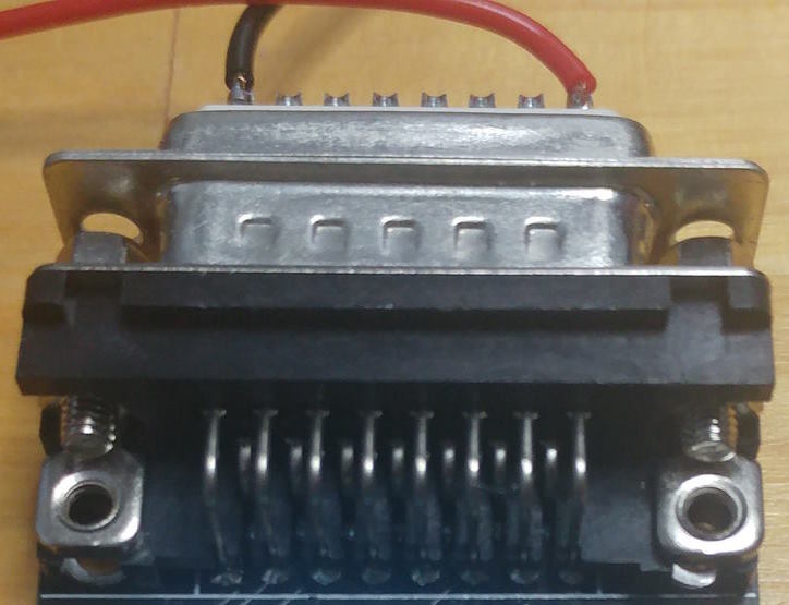
Use a female 15 pin D-Sub connector on the PCB. Note: the connectors on actual Neo Geo joysticks are longer than normal female Sub-D connectors. So, while a female connector of a Neo Geo jiystick will fit into a normal male D-Sub connector on e.g. a Supergun, a normal female 15 pin D-Sub connector will not fit into the male connector on actual AES hardware because it is too short. The workaround for this is to use a Neo Geo joystick extension cable, which are sold very cheap on e.g. AliExpress. I just needed to shorten the male plug by a few millimeters to get a good fit.
There is an SWD debug connector under the OLED display. it can be used to reprogram the controller with any appropriate flash/debug tool, e.g. ST-Link or Segger J-Link. I also included a jumper (J6) that should allow to enter the boot loader when closed during reset. According to the manual to reprogram the device through USB with an ST provided tool called STM32CubePogrammer. Admittedly, I haven't tested this at this point as I always used the SWD connection.
Anyway, I would recommend to supply the STUSB2DB15 with an according D-SUB adapter for reprogramming instead of using actual Neo Geo hardware to supply it with power.
During development, I used something like this:
All files related to this project can be found in the BitBucket
repository
https://bitbucket.org/fade0ff/stusb2db15
This is a spare time project I did without any commercial interest.
Everything is released under the Creative
Commons CC-BY license.

In a nutshell this means that you can do share, modify and use
everything released under this license even for commercial projects.
You just need to give me appropriate credit, indicate what changes you
made and agree not to try to force a more restrictive license on my
work.
See the CC BY license for details.