On a desktop PC, the GND signals of the USB ports are usually on the GND level of the electrical installation in your building.
So even if the USB device has an isolated power supply and would be isolated from ground, this isolation is bypassed by the USB connection.
There are scenarios where this is not desired, e.g. it can be necessary for measurement devices to use some potential in a circuit as reference instead of the common ground.
Besides, the direct connection of 5V and GND lines between an USB device and your PC is also problematic in case of electrical faults of the USB device.
E.g. if a catastrophic short circuit happens in the measurement device, this could damage the PC.
So there are good reasons to use an USB isolator - it's just that they are usually quite expensive. Also most of them can't supply a connected USB device.
Typically, you need to connect a power supply on the USB slave side (behind the isolation barrier), which is not very handy.
The idea was to create a relatively cheap (material cost around 20€) and simple USB isolator which fits into a small and cheap off-the-shelf case and which is able to supply a slave directly.
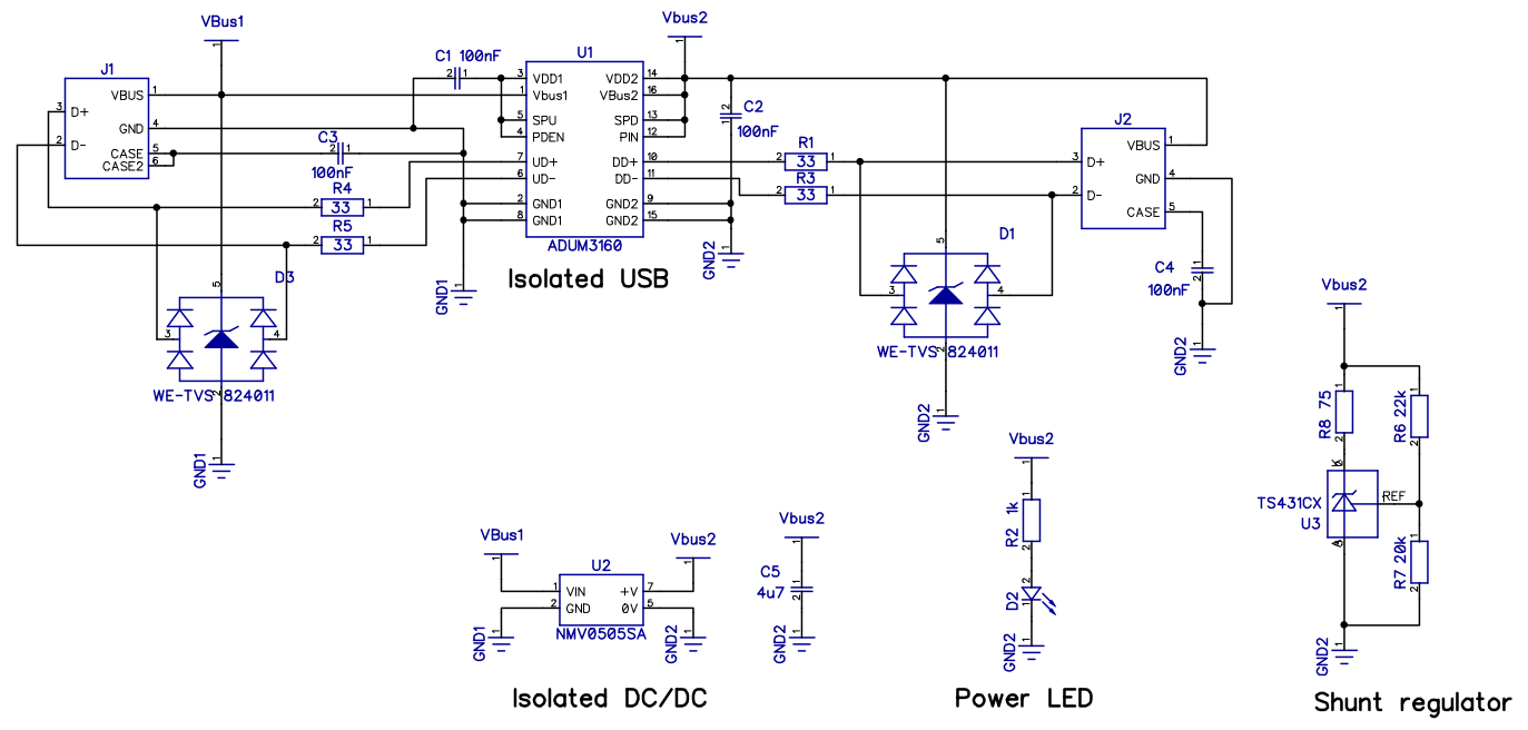
The decision regarding the isolator was pretty much straightforward, as the ADUM3160 digital isolator from Analog Devices is more or less the only easily available solution.
It supports low (1.5MBit/s) and full (12Mbit/s) speed and can withstand a voltage difference of 2500V (rms) for one minute.
For transient voltage protection, TVS diode arrays are added at the input and the output in addition to the typical serial resistors.
To be able to supply the USB device, an isolated 5V to 5V 2W DC/DC converter is added which is able to deliver 400mA at 5V.
Two possible candidates:
Murata NMK0505SAC 2W 3kV
Recom RKZ 0505S 2W 3kV
Now this would be straightforward if these DC/DC converter modules would be regulated, but they usually aren't.
Typically an isolated DC/DC only keeps its specified output voltage with a minimum of 10% load. I.e. 40mA for a 2W device and a 400mA maximum continuous load current.
Without load or at very low load current, the specified 5V output might be exceeded by up to 100% - depending on the specific device.
One idea would be to permanently sink 10% on the DC/DC output but firstly this would be a waste of energy and secondly this would also reduce the maximum current the slave could use.
So the idea is to sink the current only when the output voltage exceeds 5.25V (maximum USB VBUS voltage).
Since Zener diodes are temperature dependent, not very precise and you can't get them for any voltage, a shunt regulator TS431CX is used. It has an internal 2.5V reference and the output voltage can be configured with two resistors.
With a 22k and 20k resistor, it can be set to 5.25V
2.5V*(1+22k/20k) = 5.25V
To limit the current through the shunt regulator, a serial resistor is needed. As a rule of thumb, the voltage drop on this resistor should be the desired voltage minus 2V at the expected maximum current.
So with a current of 40mA and a voltage drop of 3.25V, this results in
3.25V/40mA = 81.25Ohm
A fitting E24 value is 75Ohm.
It's important to note that the higher the load current, the closer the output voltage of the DC/DC gets to 5V. So this is not a typical linear regulator approach.
Actually the current drained by the shunt regulator in an open load condition pretty much depends on the behavior of the DC/DC at low currents.
For a worst case assumption, let's assume a 10% scenario. So without any load (apart from the 5mA though the LED), the current drained could be as high as 40mA for a 2W type.
The TS431 can handle this easily and the 75Ohm resistor is a 0.125W type, so 40mA are still OK (P=I2R so 40mA*40mA*75 = 0.12W).
However taking into account the efficiency of the DC/DC at low currents, the current into the USB isolator will be even higher (43% higher assuming 70% efficiency).
Actually, I did some measurements with a Recom RKZ 0505S. The data sheet lacks any information about an idle current, but I measured 32mA at 5V.
Without any load (or external regulation), the output voltage is as high as 6.6V. The ADUM3160 needs around 2mA in idle mode.
The LED takes around ~5mA which however results in ~7mA on the input side due to the bad efficiency of the DC/DC at low currents.
In sum, we can expect an idle current of at least 41mA for the whole circuit without the regulation in place.
For the full circuit, I measured an input current of 62mA in idle (with 5V supply - on my PC it was just 52mA due to slightly lower voltage). Subtracting the expected 41mA that are not related to regulation, that results in 21mA flowing into the circuit due to regulation.
However, the efficiency of the DC/DC has to be taken into account to estimate the current drained by the shunt regulator. With an assumed 70% efficiency at low loads, it's probably around 13mA.
Then again, the voltage drop on the 75Ohm resistor can be measured directly to determine the current. With a 5V USB voltage I measured a 1.3V drop which means 17mA.
For the slightly lower USB voltage on my PC I measured a voltage drop of 1.1V which means a current of ~15mA.
So there's no need to worry about the 75Ohm resistor since the current needed to get a stable 5.25V output is only around 15-17mA which means 17-22mW at the resistor.
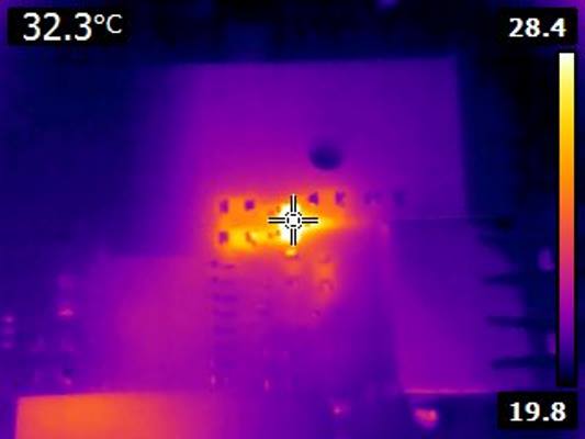
A quick look with a thermal image camera shows nothing unexpected. The TS431 gets a bit warmer (32°C) but the 75Ohm resistor is just slightly above room temperature.
Note that a drawback of the DC/DC approach is that it violates the minimum current requirements in USB suspend where the current must not exceed 2.5mA which is not possible if the DC/DC alone needs much more than that.
While it's common for USB devices to exceed this idle current or not support suspend modes at all, this could cause issues with low power modes on Notebooks, especially for Win8 and Win10.
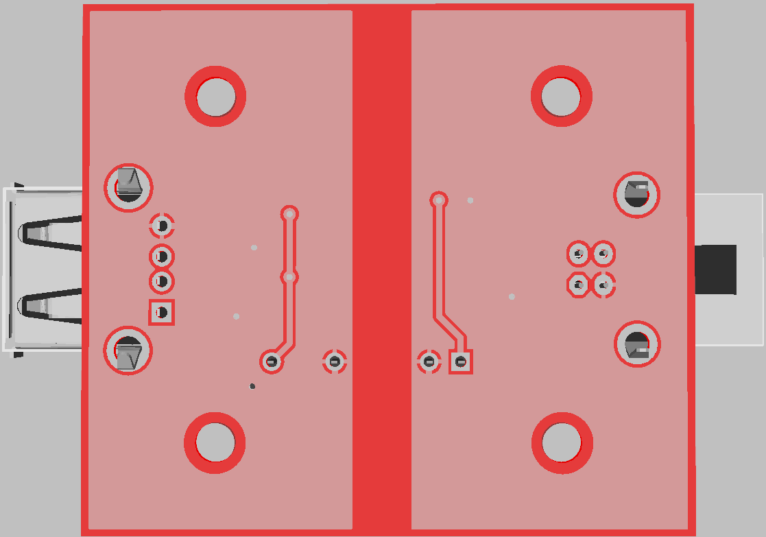
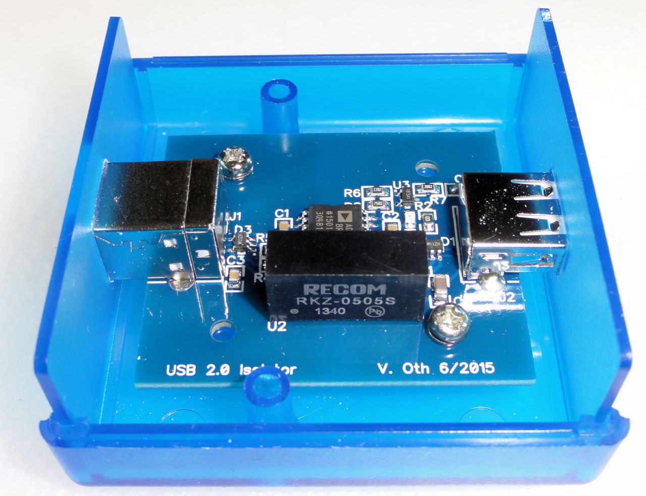
Schematic and Design were done with DipTrace.
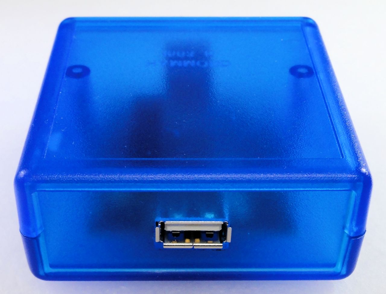
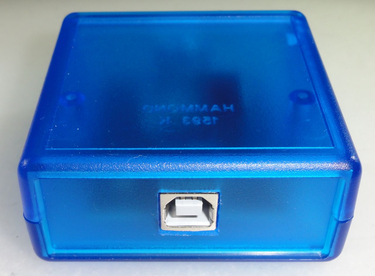
I decided to use an USB-B connector on the host side and USB-A on the slave side - mainly because 90% of my USB cables are just like this.
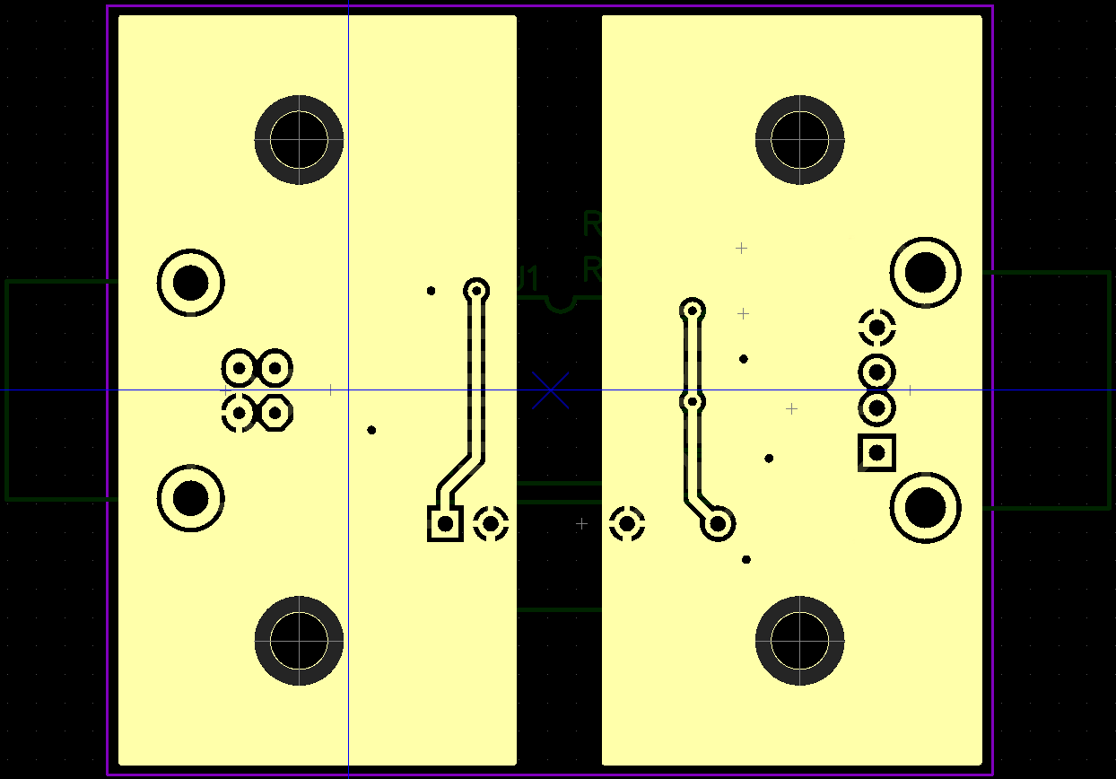
I tried to keep the two sides as far apart as possible to not degrade the isolation.
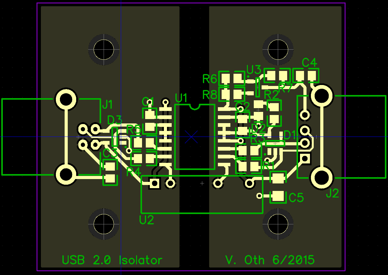
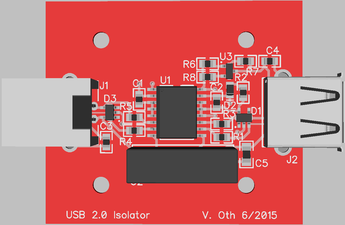
Just a preview of the final isolator.
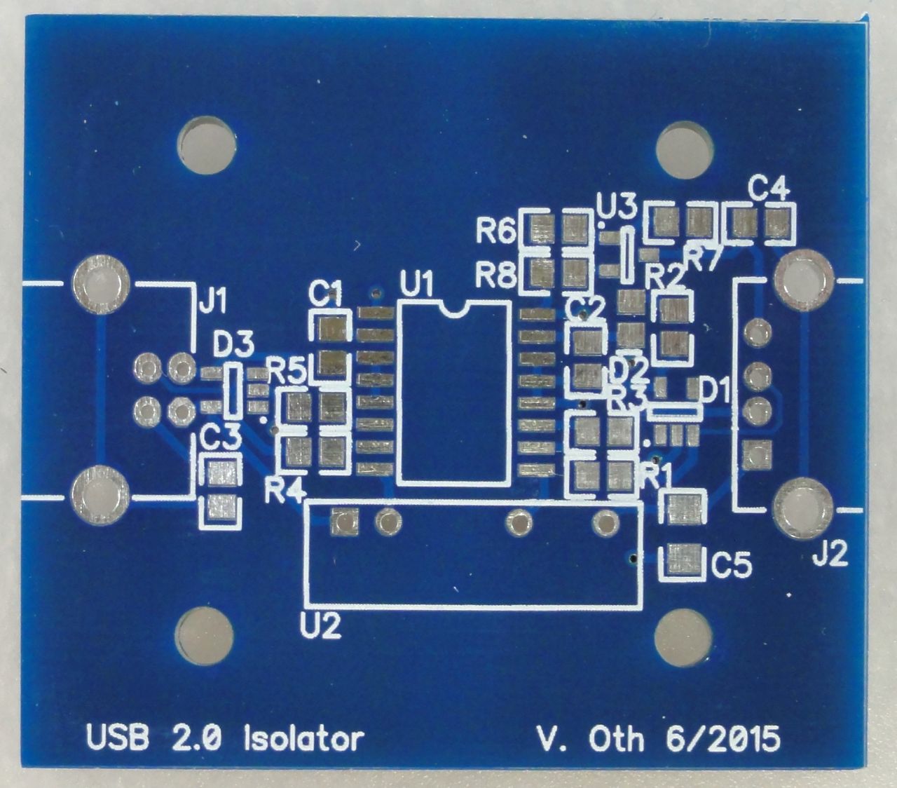
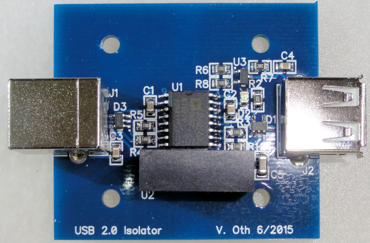
Ordered them at Elecrow, no problem as usual. Some crinkles in the solder resist but otherwise pretty good quality.
The case I selected is a Hammond 1593K . It's available in different colors, e.g. in black and transparent blue.
1593KBK (black)
1593KTBU (transparent blue)
I created a CAD drawing of the front/back panels to be able to get them cut from acrylic at Formulor, but for the moment I just used a drill and file to get the holes done.
All files related to this project can be found in the BitBucket repository
https://bitbucket.org/fade0ff/usb-isolator
This is a spare time project I did without any commercial interest.
Everything is released under the Creative
Commons CC-BY license.

In a nutshell this means that you can do share, modify and use everything
released under this license even for commercial projects.
You just need to give me appropriate credit, indicate what changes you
made and agree not to try to force a more restrictive license on my work.
See the CC BY license for details.